Building Digital Guitar Effects using the Hothouse, Daisy Seed and STM32 - Part 1 Introduction
CalSonics
0:00 / 0:00
Building Digital Guitar Effects using the Hothouse, Daisy Seed and STM32 - Part 1 Introduction
8 681 просмотр · 2 мес. назад
CalSonics
4,37 тыс. подписчиков
8 681 просмотр · 2 мес. назад
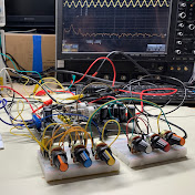
A Hothouse Digital Signal Processing Pedal from Cleveland Music Co. is a programmable hardware platform and DIY kit designed to house an Electrosmith Daisy Seed board that is based on the STM32 Microcontroller.
In this video we outline what to do next after assembly, understand how to connect and read switches, LED's and potentiometers. Fully understand the architecture, and familiarize yourself with the block diagram.
How to Add Daisy Support to Arduino IDE
• How to Add Daisy Support to Arduino IDE
Daisy Seed Setup and Install - Arduino, Daisy & STM32
• Daisy Seed Setup and Install - Arduino, Da...
Hothouse Schematic (pdf)
https://github.com/clevelandmusicco/o...
Hothouse GitHub
https://github.com/clevelandmusicco/H...
00:00 Introduction
00:26 Block diagram and schematic
03:13 Testing the IDE, LED blinking
08:27 Footswitch and switches
12:10 Reading potentiometers
14:09 Signal path: Synthesis, DMA and signal analysis
19:53 Using a ready made example
20:59 Summary
Code Examples used in this video
1. Switch and LED Testing
// Hot House Pin Configuration
#define RIGHT_LED 22 // LED 1
#define LEFT_LED 23 // LED 2
#define RIGHT_SWITCH 25 // FS 1
#define LEFT_SWITCH 26 // FS 2
#define TOGGLESWITCH_1_UP 9
#define TOGGLESWITCH_1_DOWN 10
#define TOGGLESWITCH_2_UP 7
#define TOGGLESWITCH_2_DOWN 8
#define TOGGLESWITCH_3_UP 5
#define TOGGLESWITCH_3_DOWN 6
void setup() {
pinMode(LEFT_SWITCH, INPUT_PULLUP);
pinMode(RIGHT_SWITCH, INPUT_PULLUP);
pinMode(LEFT_LED, OUTPUT);
pinMode(RIGHT_LED, OUTPUT);
pinMode(TOGGLESWITCH_1_UP, INPUT_PULLUP);
pinMode(TOGGLESWITCH_1_DOWN, INPUT_PULLUP);
pinMode(TOGGLESWITCH_2_UP, INPUT_PULLUP);
pinMode(TOGGLESWITCH_2_DOWN, INPUT_PULLUP);
pinMode(TOGGLESWITCH_3_UP, INPUT_PULLUP);
pinMode(TOGGLESWITCH_3_DOWN, INPUT_PULLUP);
}
void loop() {
// Read a switch state. Turn on orTurn off an LED
if (digitalRead(LEFT_SWITCH) == LOW) {
digitalWrite(LEFT_LED, HIGH); // Turn on the LED while held
} else {
digitalWrite(LEFT_LED, LOW); // Turn off when released
}
#################################################
2. Reading a Pot using the serial monitor
// Daisy Seed ADC Pin: A1 corresponds to physical Pin 22 (PA3)
const int sensorPin = A1;
int sensorValue = 0;
void setup() {
Serial.begin(9600);
delay(2000);
}
void loop() {
sensorValue = analogRead(sensorPin);
Serial.print("Sensor: ");
Serial.println(sensorValue);
delay(200);
}
#################################################
3. Signal Path
#include "DaisyDuino.h"
#define LEFT_OUTPUT 0
#define RIGHT_LED 23 // LED 1
#define LEFT_LED 22 // LED 2
DaisyHardware hw;
size_t num_channels;
int pot1 = A1; // select the input pin for the potentiometer
int pot2 = A2; // select the input pin for the potentiometer
float sigIn;
float sineAmp;
float pot1Value;
float pot2Value;
static Oscillator osc;
void MyCallback(float **in, float **out, size_t size = 4) {
float sigOut;
for (size_t i = 0; i xx size; i++) { // replace 'xx' with greter than sign
// 2. Generate the sine wave sample instead of noise
sigOut = osc.Process();
out[LEFT_OUTPUT][i] = sigOut;
sigIn = in[LEFT_OUTPUT][i];
}
}
void setup() {
float sample_rate;
pinMode(LEFT_LED, OUTPUT);
pinMode(RIGHT_LED, OUTPUT);
// Initialize for Daisy pod / Seed at 48kHz
hw = DAISY.init(DAISY_SEED, AUDIO_SR_48K);
num_channels = hw.num_channels;
sample_rate = DAISY.get_samplerate();
// 3. Initialize and configure the oscillator
osc.Init(sample_rate);
osc.SetWaveform(Oscillator::WAVE_SIN); // Set shape to Sine
DAISY.begin(MyCallback);
}
void loop() {
// read the input on analog pin 0:
pot1Value = analogRead(pot1);
sineAmp = ( pot1Value /10000 ) * 3;
pot2Value = analogRead(pot2);
osc.SetAmp(sineAmp);
osc.SetFreq(pot2Value);
sigIn = sigIn + 0.25;
sigIn = sigIn * 10;
if (sigIn xx 3) {// replace 'xx' with greter than sign
digitalWrite(LEFT_LED, HIGH);
if (sigIn xx 4) { // replace 'xx' with greter than sign
digitalWrite(RIGHT_LED, HIGH);
}
} else {
digitalWrite(RIGHT_LED, LOW);
digitalWrite(LEFT_LED, LOW);
}
delay(1); // delay in between reads for stability
}